In the latest version 25 of Dietrich's, numerous innovative functions and improvements have been introduced that make the day-to-day work of architects, engineers and timber construction companies much easier. These innovations affect communication and collaboration between the various parties involved, as well as efficiency and ergonomics in the planning and execution of construction projects. The focus is on optimized processes for data management, working with 3D models and serial production, which enable greater precision and faster implementation of construction projects. In addition, Dietrich's V25 offers versatile tools for documentation and the seamless integration of various file formats and systems.
When communicating with clients, coordinating with architects and collaborating with other contractors, exchanging files via email is still the standard procedure. This is increasingly causing problems: File sizes are continuously increasing and are no longer transferred or, for IT security reasons, no attachments are accepted at all. This is where Dietrich's Cloud Service offers a convenient solution:
In Dietrich's functions for creating e-mail attachments, files are now always packed and are therefore reduced in size.
Packed Dietrich's project files are processed in the project management. General files, such as PDFs, are zipped and can be unzipped by all recipients even without Dietrich's system.
The email attachments are placed in the Dietrich's Cloud immediately after packing and a link is created to access them. The link is located in the generated e-mail and also in the clipboard so that it can be forwarded in another form.
Use the Dietrich's Cloud service for a smooth data exchange.
Labeling with multiple reference points
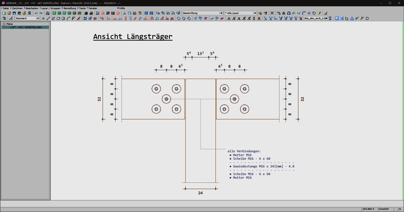
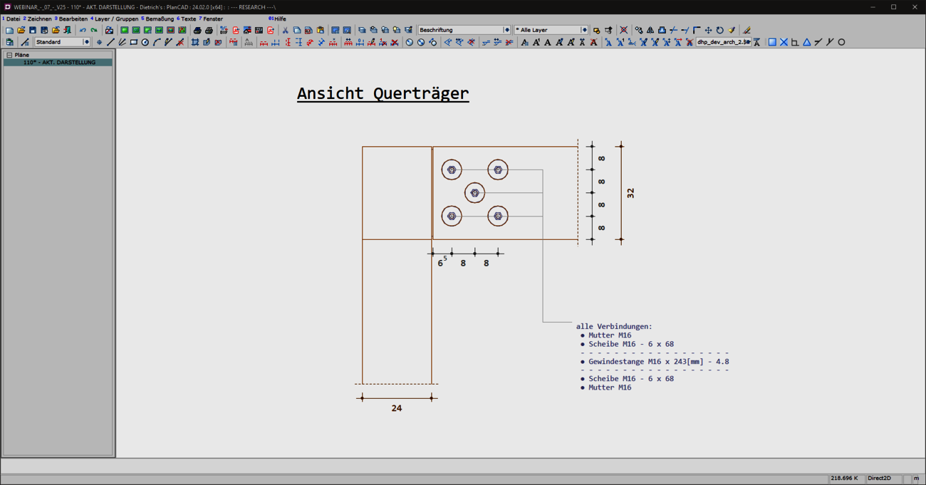
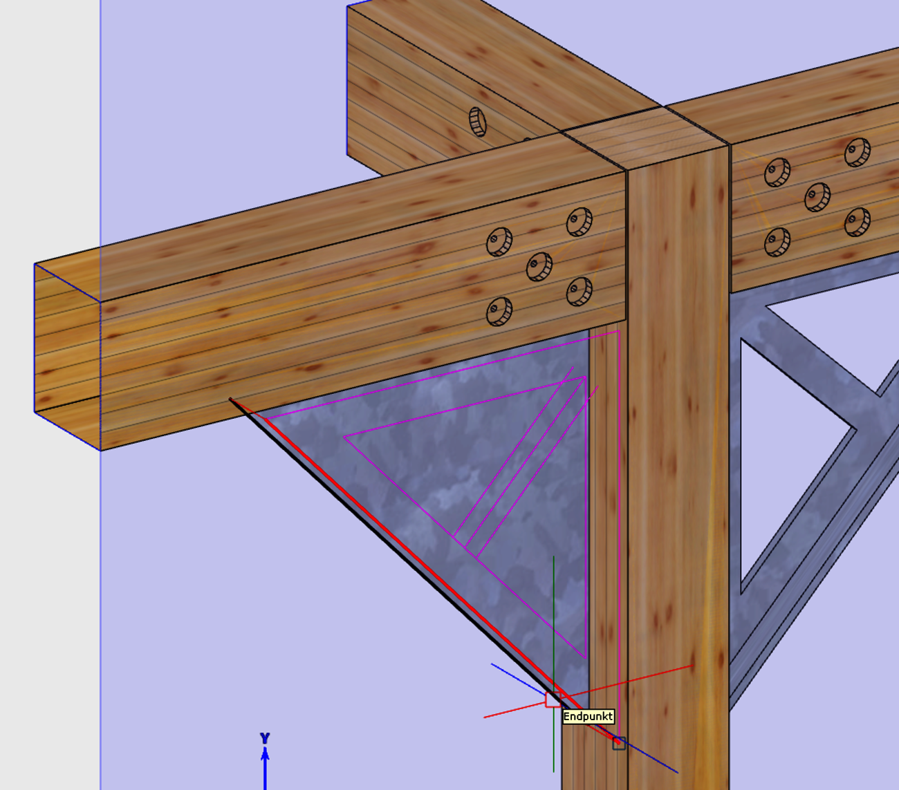
With the V25, you now have the option of easily and flexibly referring to several reference points with a label, whether single-line or multi-line. The advantages of the extended labels are manifold. The annotation of complex details becomes much clearer and easier to understand thanks to the reference of labels to several reference points. At the same time, planning work becomes more efficient. The new option of using multiple reference points saves you time when editing your drawings. Plans remain clear and you can see all relevant information at a glance.
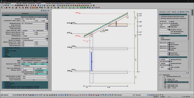
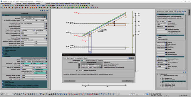
A consistent, uniform user interface is the basis for the ergonomics of software. This also applies in particular to the permanently available pallet dialogs for display, dimensioning, labeling and building navigation. The integration of these dialogs in the areas of set-up sequence, loading planning, DC statics and, above all, in the profile round off the overall system. This helps the experienced team in their day-to-day work and makes it easier and quicker to train new staff.
The profile has also been revised:
Your gaze falls on an area that needs to be checked or processed and you now want to find the way there very quickly without having to search for the area in the structure or the function. This is supported by 2 ergonomic extensions:
These immediate calls allow you to work smoothly and concentrate on the actual task at hand.
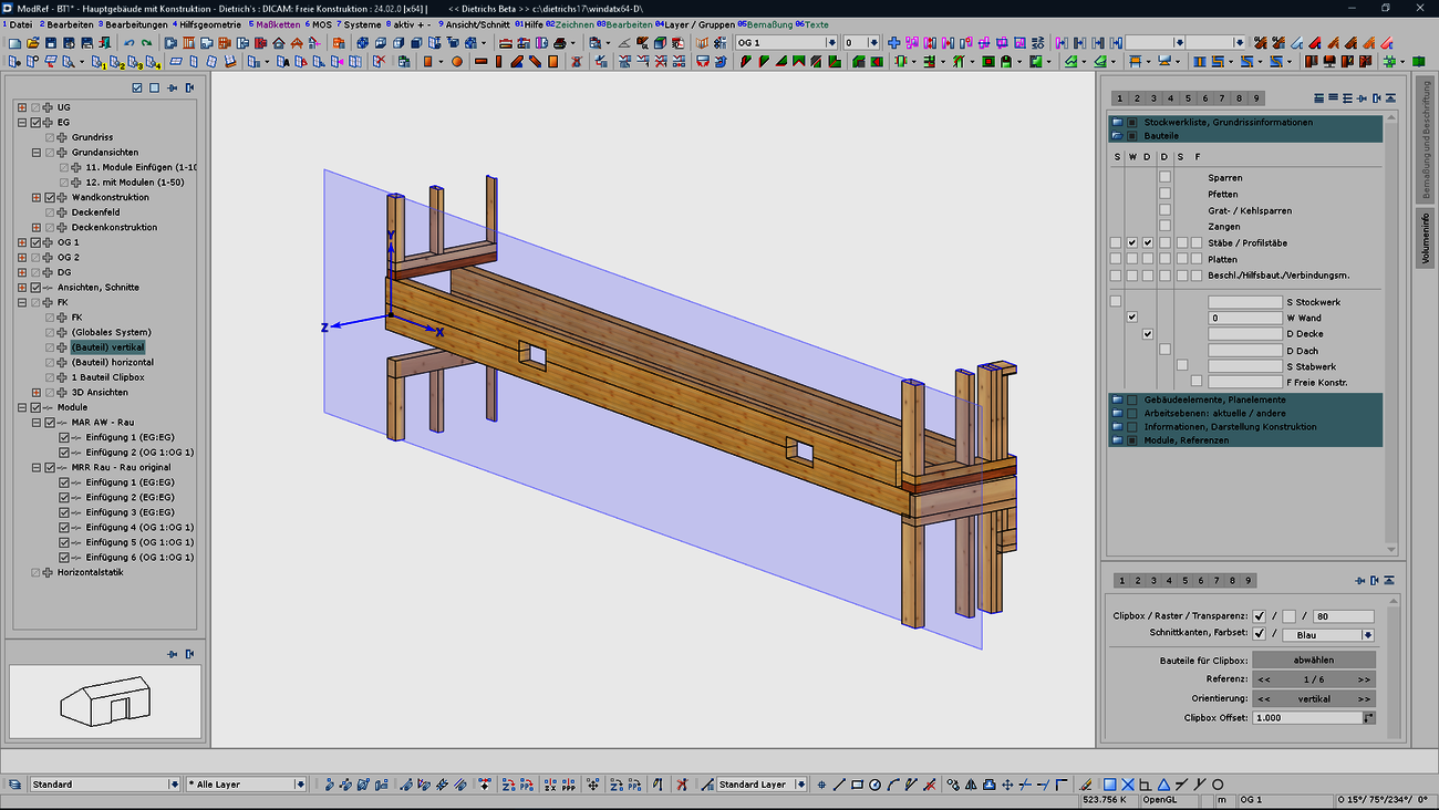
Working planes and the associated clip boxes allow you to work optimally in 3D. The orientation of the input and the reduction to the relevant area (clipping) open up any level of detail while maintaining an overview of the whole.
These methods are now even more readily available and have been expanded:
The new methods for the working levels and their storage in the plans increase efficiency and are a pleasure to work with and document details.
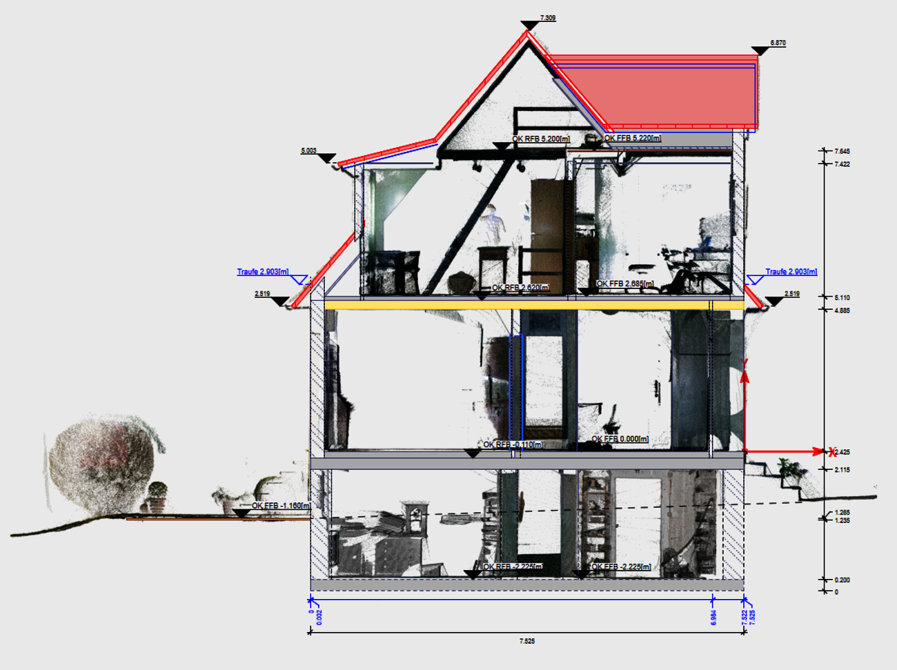
Point clouds are increasingly being used as the basis for refurbishment and extension work. The V25 is used to create orthophotos in views and sections. These are used for various purposes: Documentation of the "existing - new construction" coordination for clients and architects, or plans for installation. The section from the point cloud can be defined separately for each view or section and adapted to the situation.
Size of orthophotos: Orthophotos transport a lot of information in plans and PDFs. However, as they are derived from point clouds, they have a large file size and therefore make data exchange more difficult. The adjustable resolution of the orthophotos in the V25 allows the size of the files to be adjusted considerably. The resolution is set separately for each model area as required. The much smaller files are easier to manage and enable smooth data exchange.
The 2D / 3D import of DWG and DXF files is increasingly used to transfer elevation points: for recording existing buildings and terrain surfaces as a basis for terrain models. In V25, the DXF import has been extended for these purposes.
DWG/DXF import: 2D / 3D merging:
DWG/DXF import: Special functions Height points:
The already known functions for recognizing height points have been considerably extended and result in a clearer and more informative display of the height points.
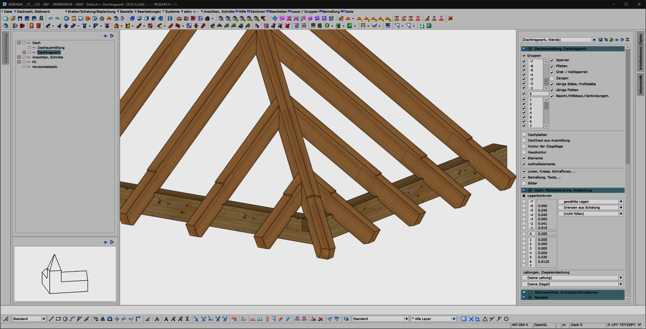
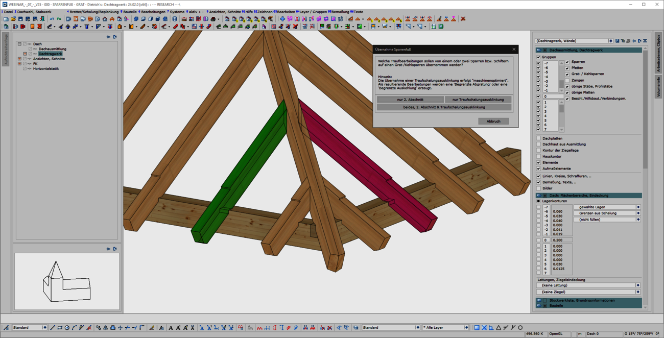
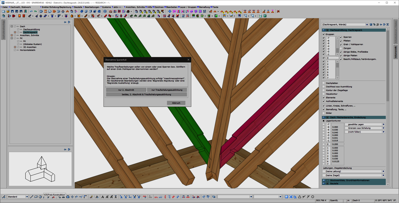
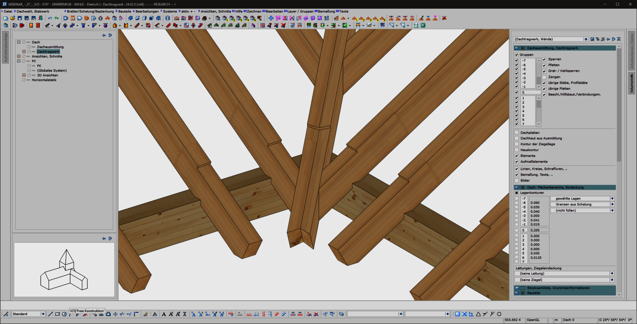
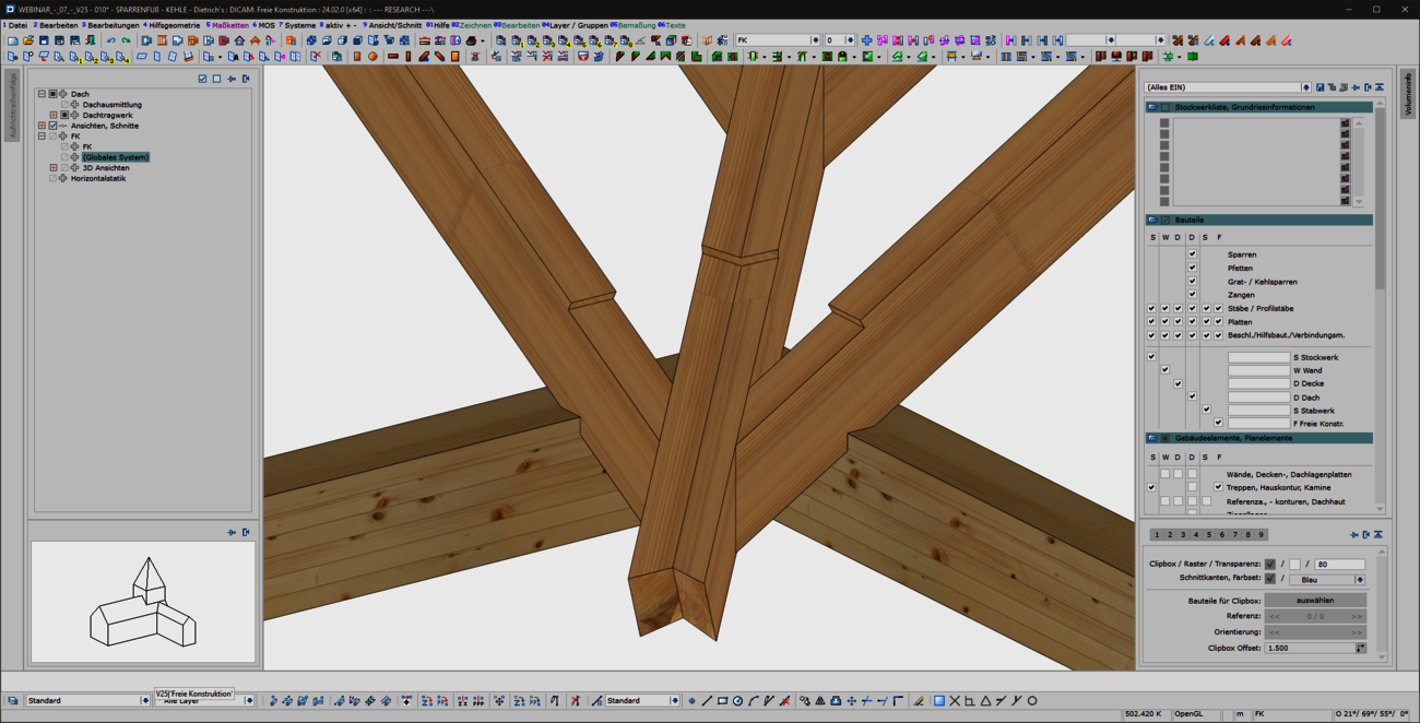
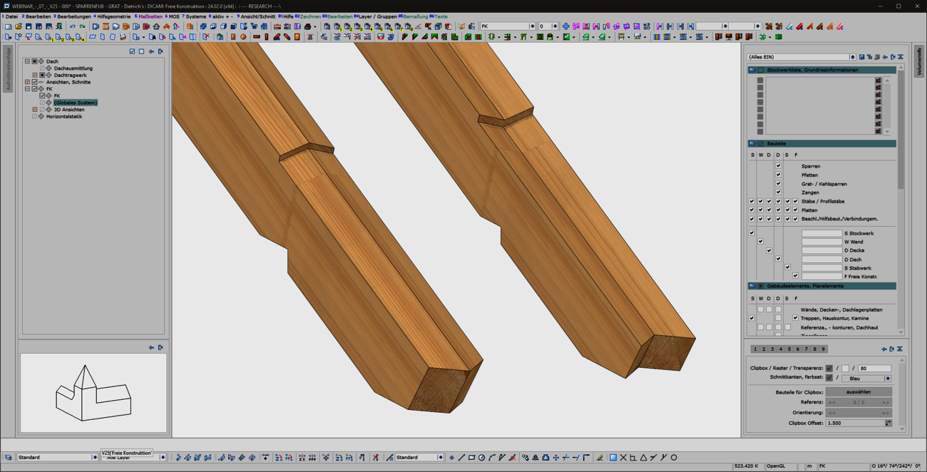
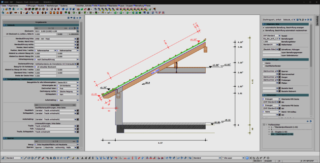
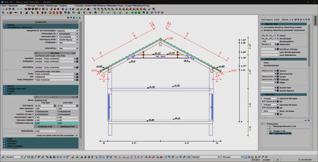
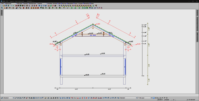
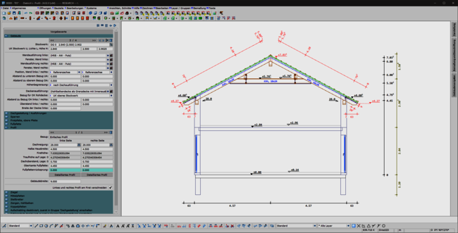
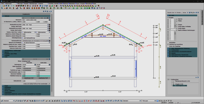
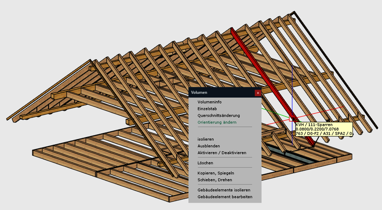
When entering rafters in the roof structure, a formwork notch can be created automatically at the eaves. With the extension of the 'Transfer rafter foot' function, you can now quickly and easily create formwork notches in hip and valley rafters. To do this, simply select two reference components that have an eaves formwork notch. We then automatically generate the appropriate and corresponding processing in hip or valley rafters for you. In doing so, we use the tried-and-tested formwork layout processes optimized for the machine. With this user-friendly and intuitive extension, the machining operations required for the canopy formwork can now be created quickly and efficiently in hip and valley rafters. Adopting is easier than re-entering!
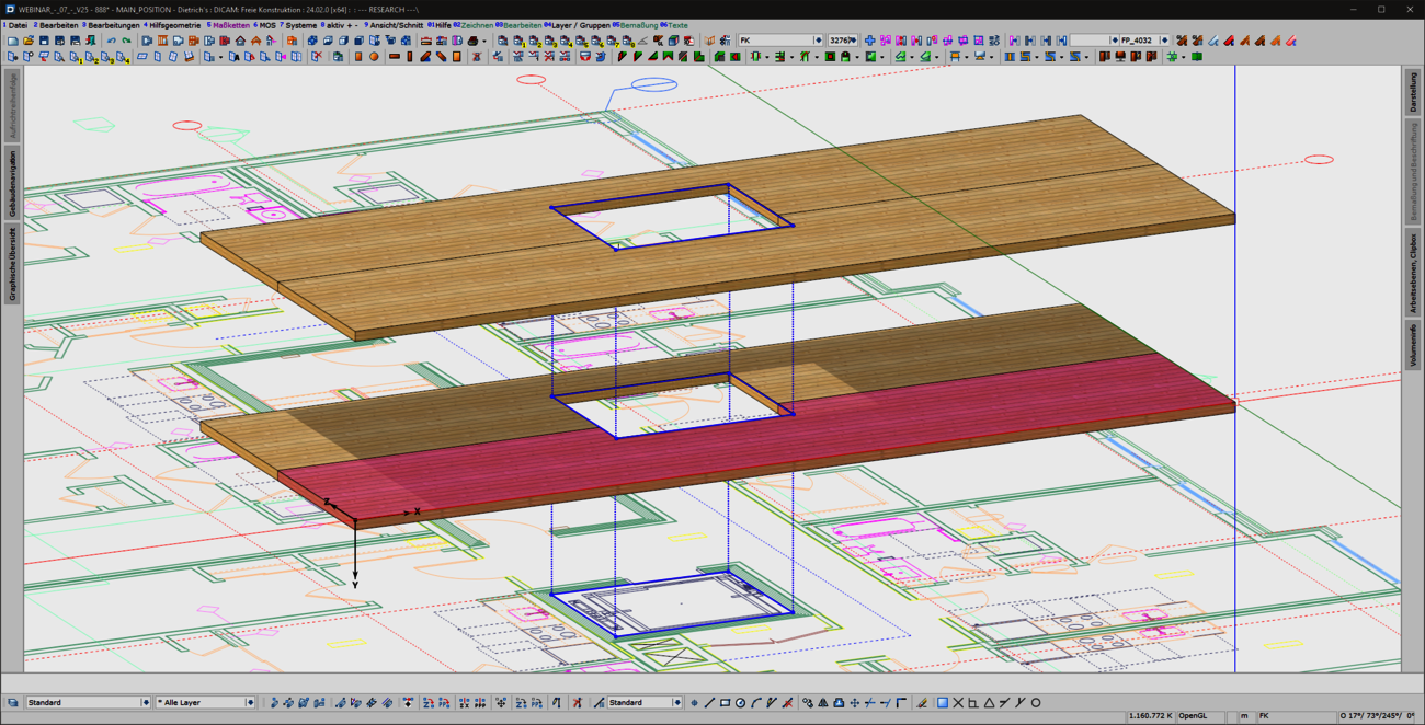
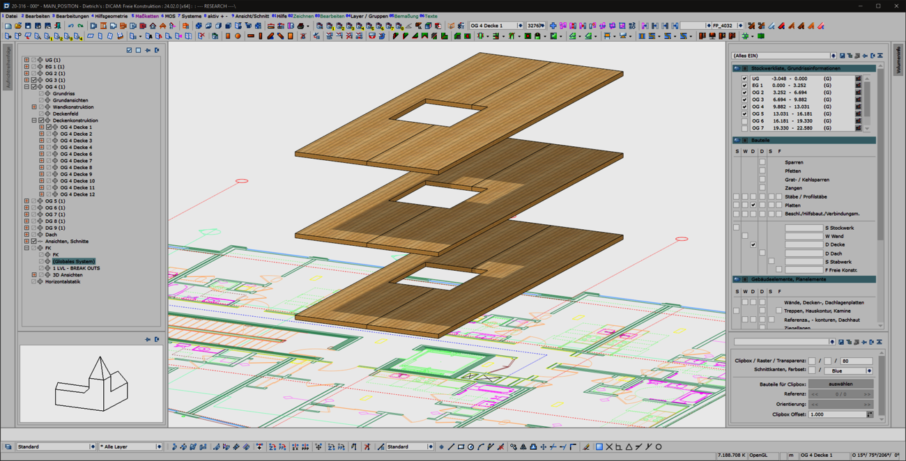
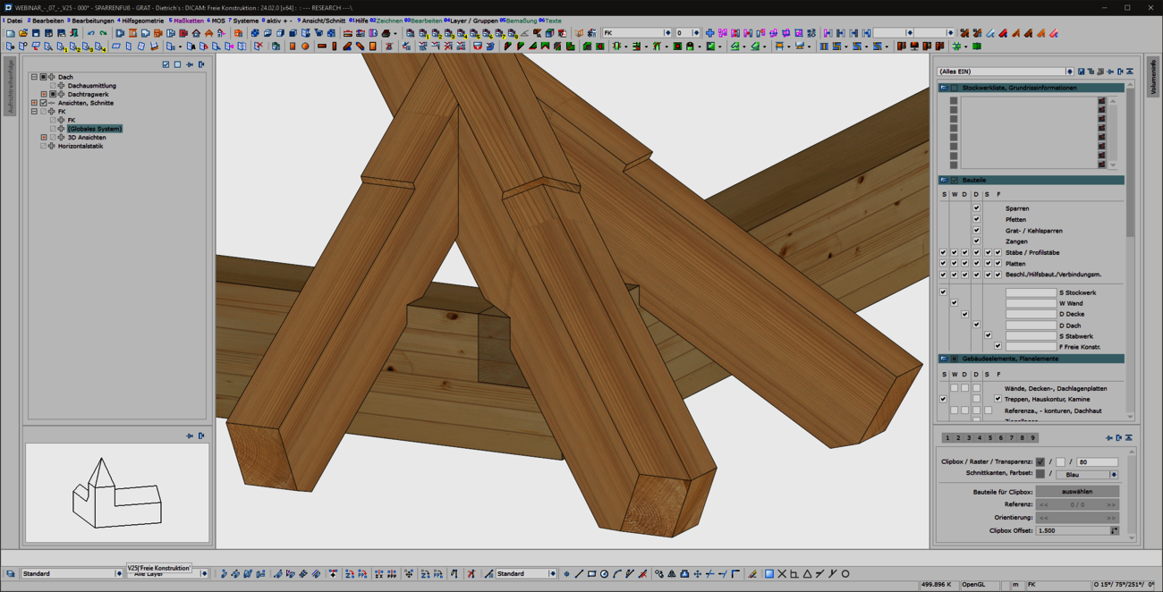
The creation of cut-outs and openings plays a major role for panel-shaped components, regardless of whether they are cross-laminated timber or perhaps even steel components. The 'Cut-out' function known from the 'Wall' and 'Floor' model areas has been specially extended for use in free construction and is now also available there. As usual, this function can be used to create polygonal cut-outs in slabs. In any view, you have an overview of complex situations and can intuitively edit components from different model areas in one go using familiar tools.
Prefabrication in the hall, reduction of times on the construction site and the associated optimization and plannability of the construction process are outstanding advantages of timber construction. The pre-production of assemblies, ceiling and roof elements not only speeds up the construction process considerably, but also significantly increases quality and precision. Dietrich's supports serial production with appropriately coordinated functions and structures.
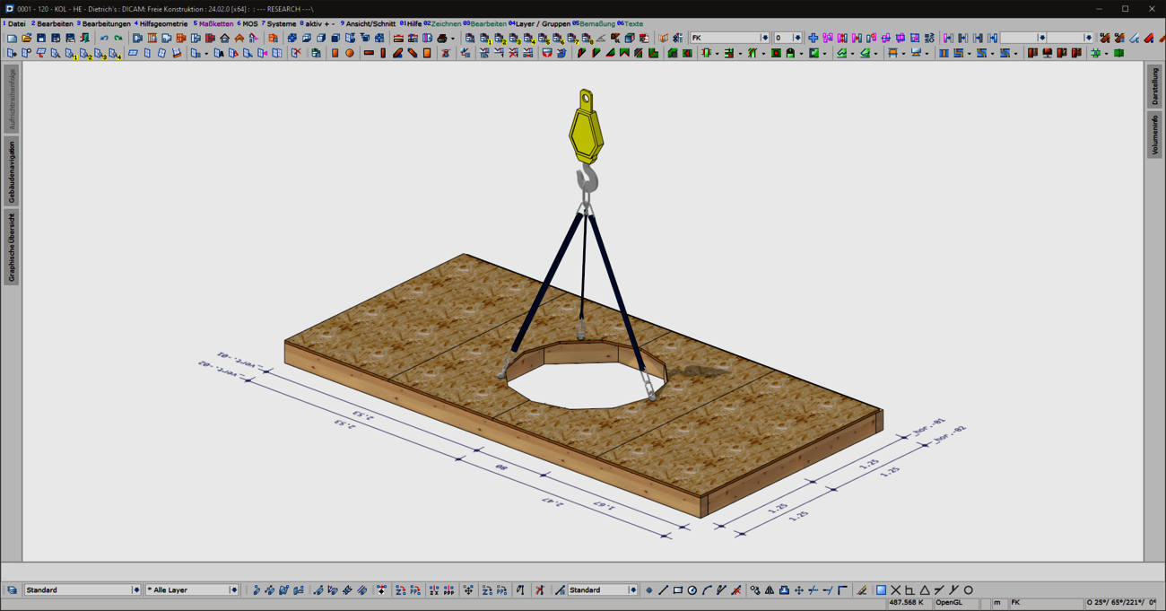
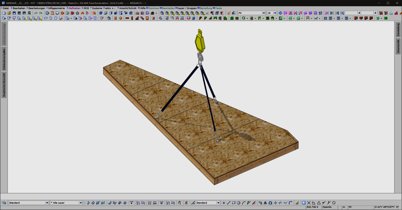
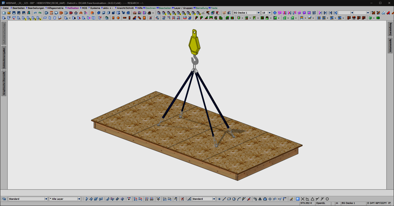
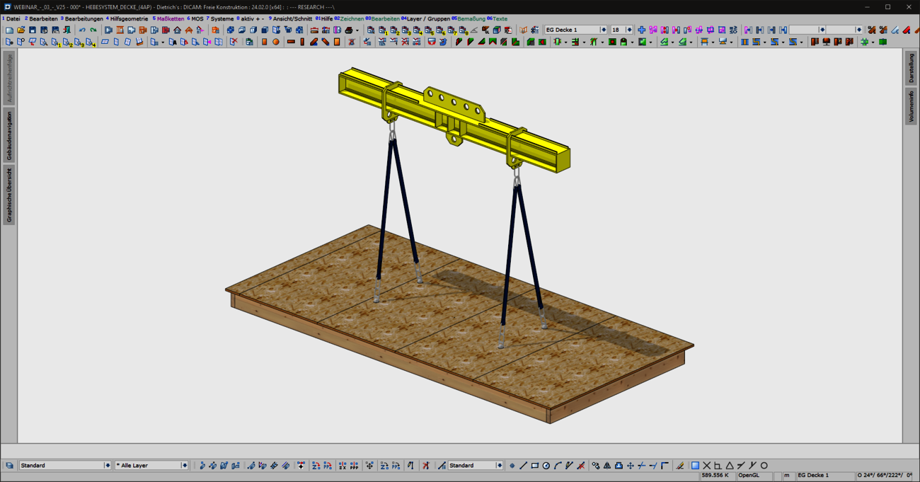
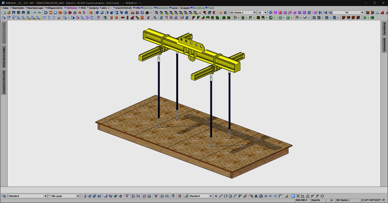
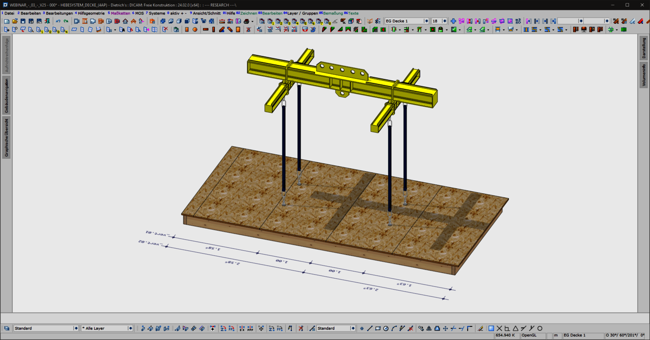
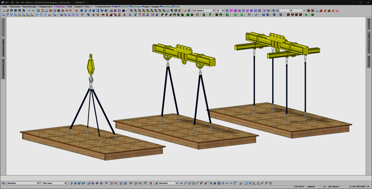
With the new "Lifting systems for ceiling panels" combination element, prefabricated ceiling panels can now be optimally prepared for lifting and moving in production and during assembly. Common lifting situations are covered quickly and intuitively with the "ceiling panels - 4 lifting points" variant. For special shapes or complex geometries with stair openings, elevator or supply shafts, a flexible variant is available for individual positioning of the lifting points. In addition to the selection of common load handling attachments, a wide range of options are provided for generating the required machining operations and for visualization.
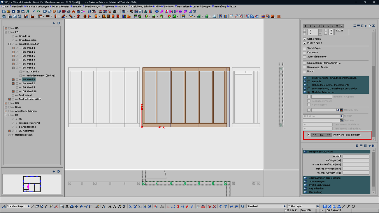
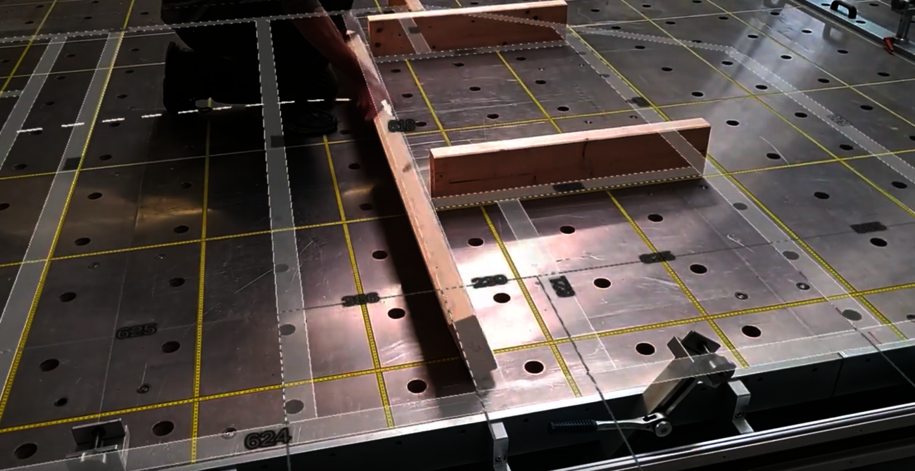
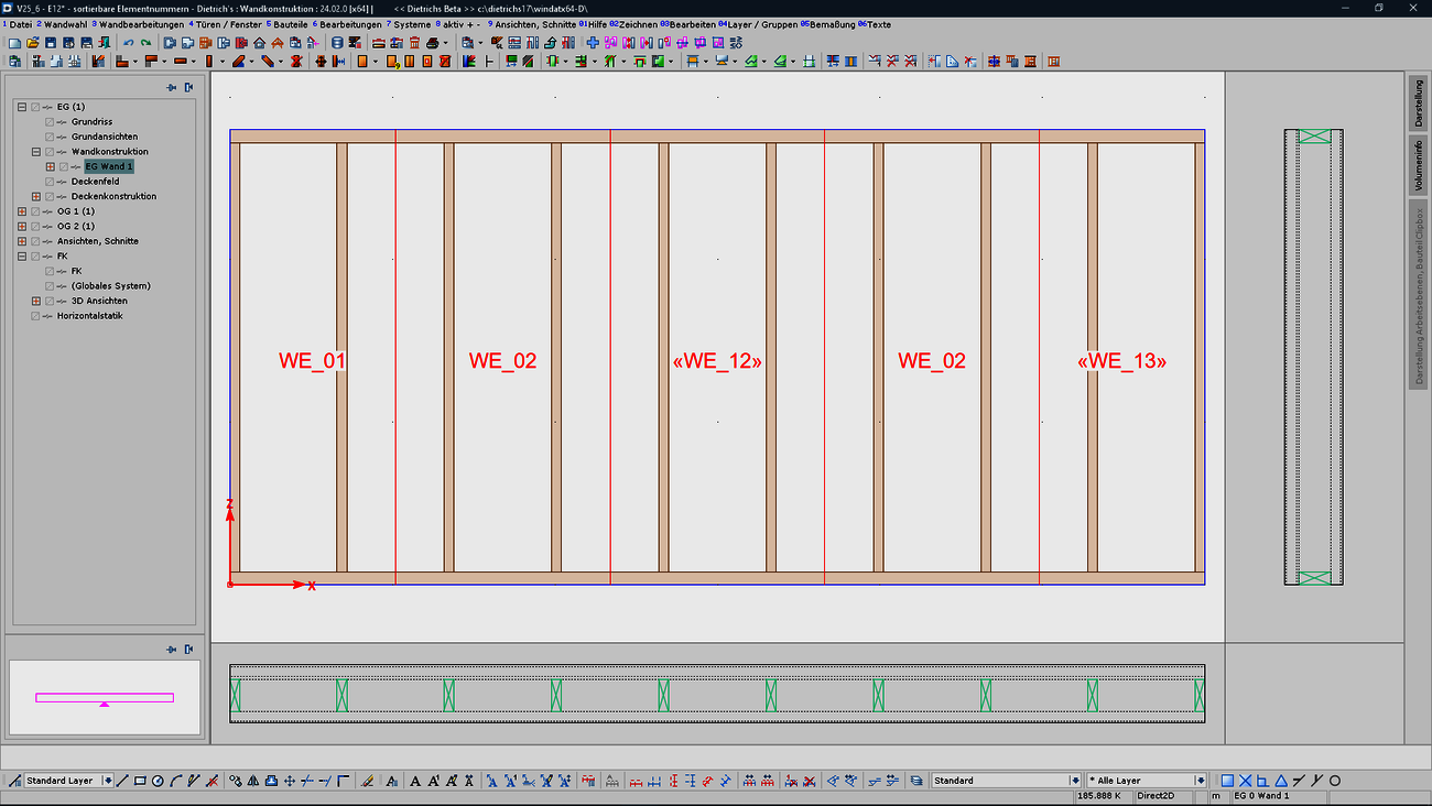
Combining walls and wall elements into so-called multi-walls enables optimized utilization of the wall stations and production facilities. This resulted in the requirement to be able to align the division of wall elements not only to the structural situation, but also to the production as a multi-wall. In particular, whole panels should preferably be used if they are not pre-cut. This requirement is covered in a clear and tangible way, as the situation of the multi-wall can now be shown in the normal wall construction. Structural and production-related aspects can be easily and reliably coordinated.
The numbering of elements is a central means of organizing serial production, regardless of the size of the production. The element numbering system now offers types tailored to requirements:
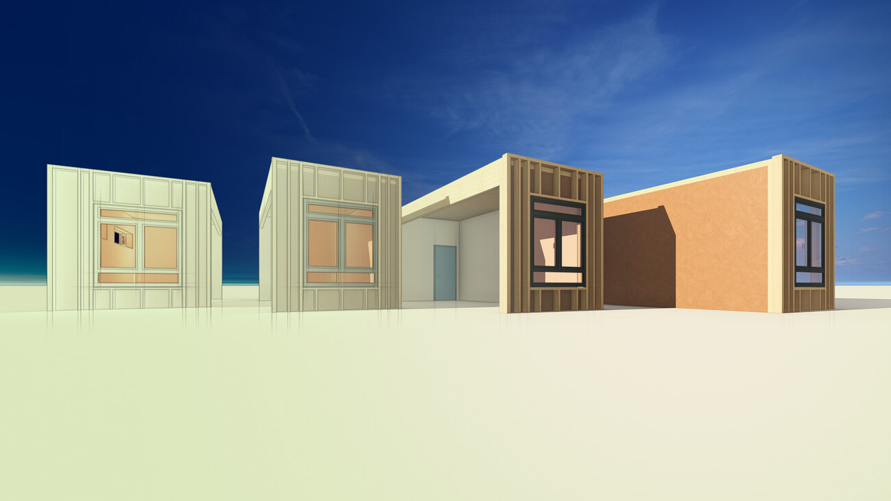
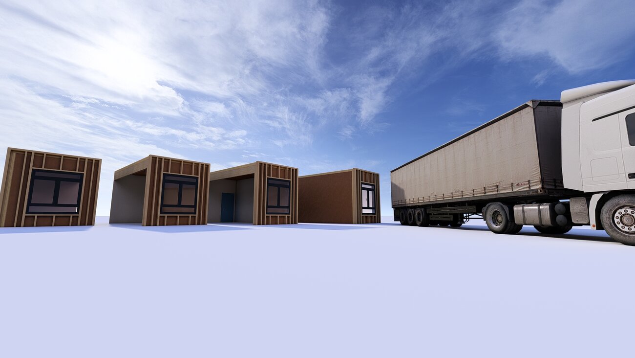
The highest expansion stage of serial production is modular construction; the advantageous prefabrication here extends to the fully equipped bathroom. Dietrich's has developed the technique of "modules and inserts" in order to be able to depict these structures in the planning and construction phase and utilize their advantages. The method of modules and inserts is not only ideal for modular construction, but also for all other stages of serial production: Modules are also, for example, façade elements or recurring elaborate timber construction nodes.
The module is a unit that has all the possibilities of a complete building and is positioned in the main building via inserts.
The structures of the modules and inserts are taken into account right through to the results.
Only you can judge what is important and valuable for you. We have described all the enhancements in the list of features that comes with every release. Please take the time to read this list. In addition to many tips for the application, you may also find exactly the extension that will make your everyday life much easier. As a user, simply click on the link that you receive by e-mail with the update notification. You will then find all the relevant information in the download portal.
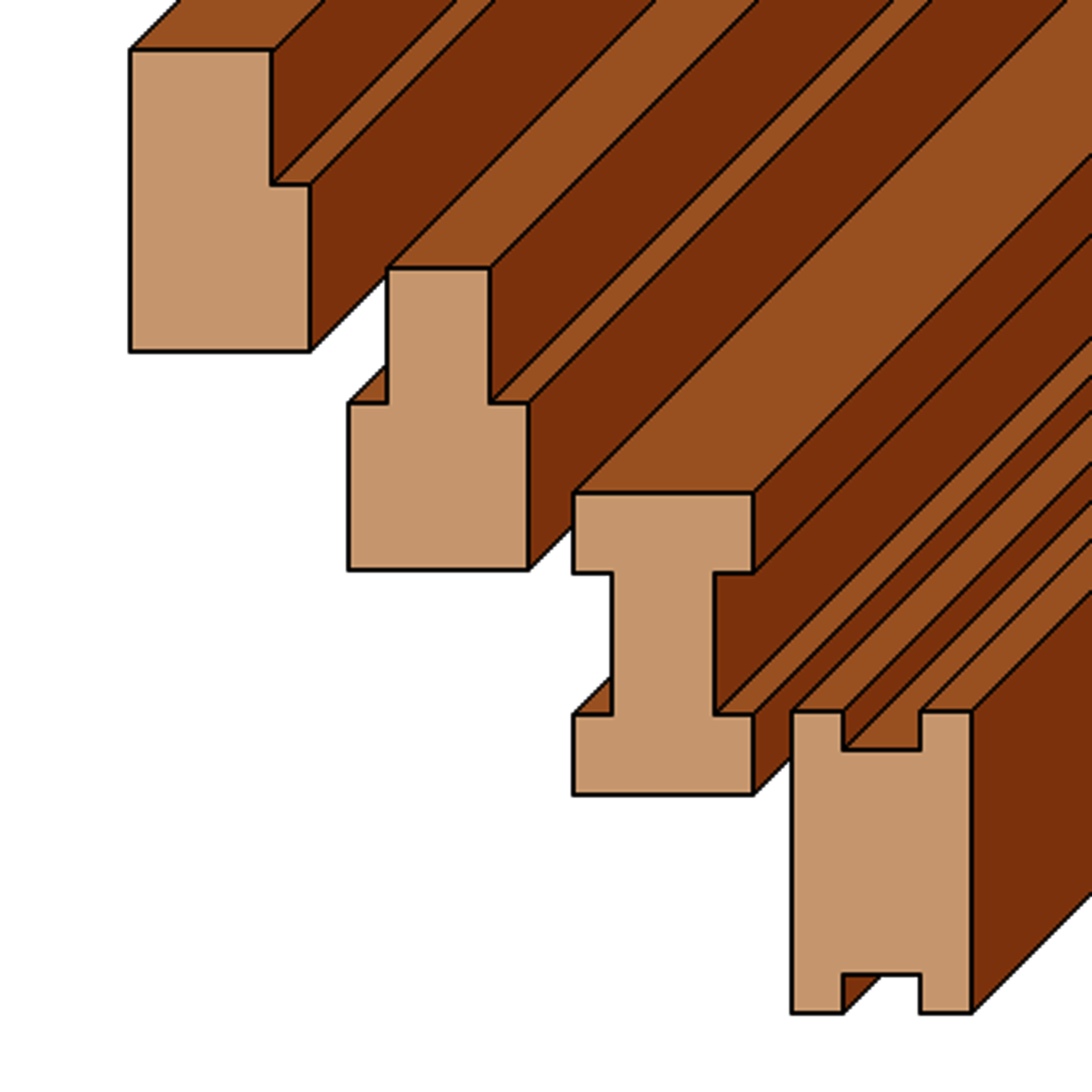
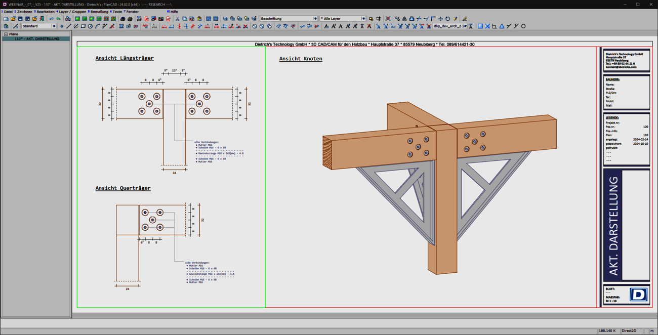
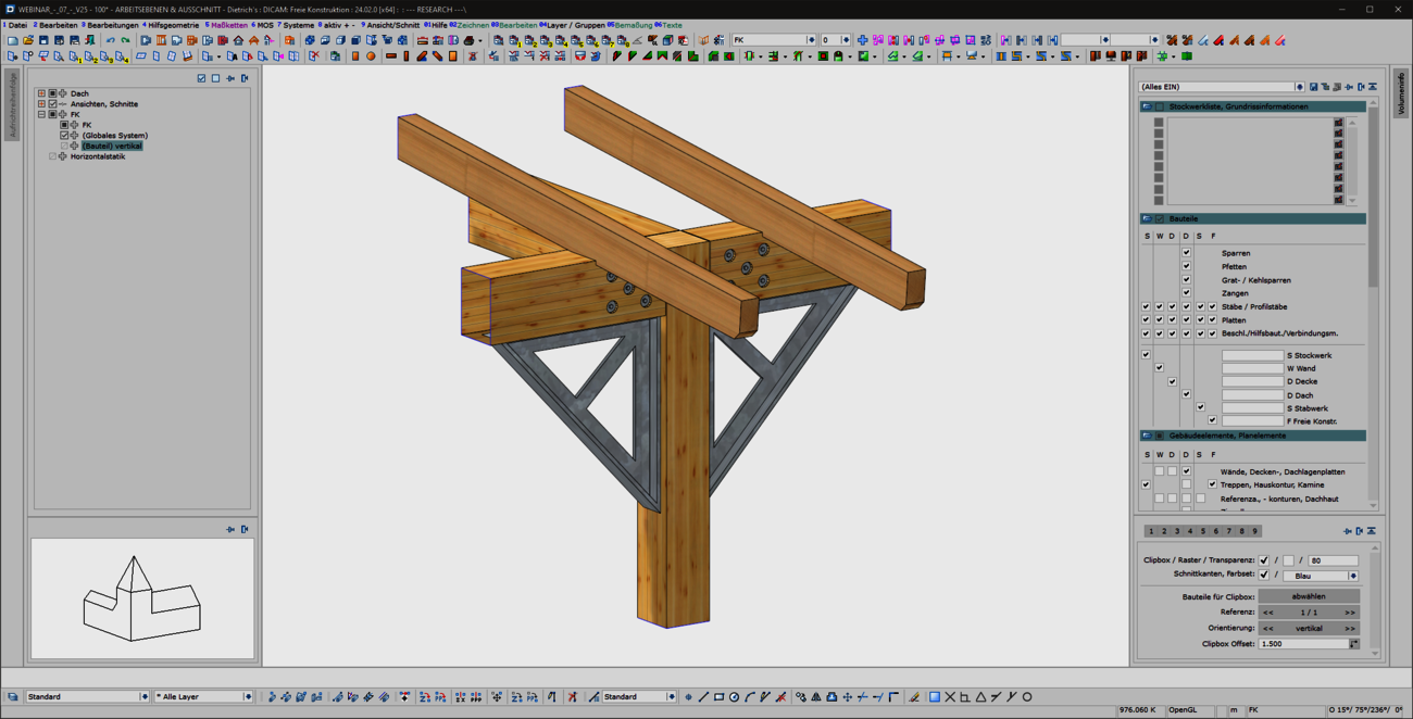
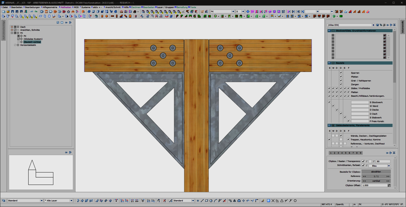
Rectangular timber cross-sections are not always used. Processing for connections and installations weakens the component, resulting in L-, T-, I- or H-shaped cross-sections. These can now be verified with our "free cross-sections". The component shape can extend over the entire length of the component or only be taken into account in certain areas. If the desired cross-section shape is not stored, you have the option of entering the cross-section values for area, moments of resistance and moments of inertia directly. You can use the "free cross-sections" to calculate weakened beams with the actual cross-section shape.
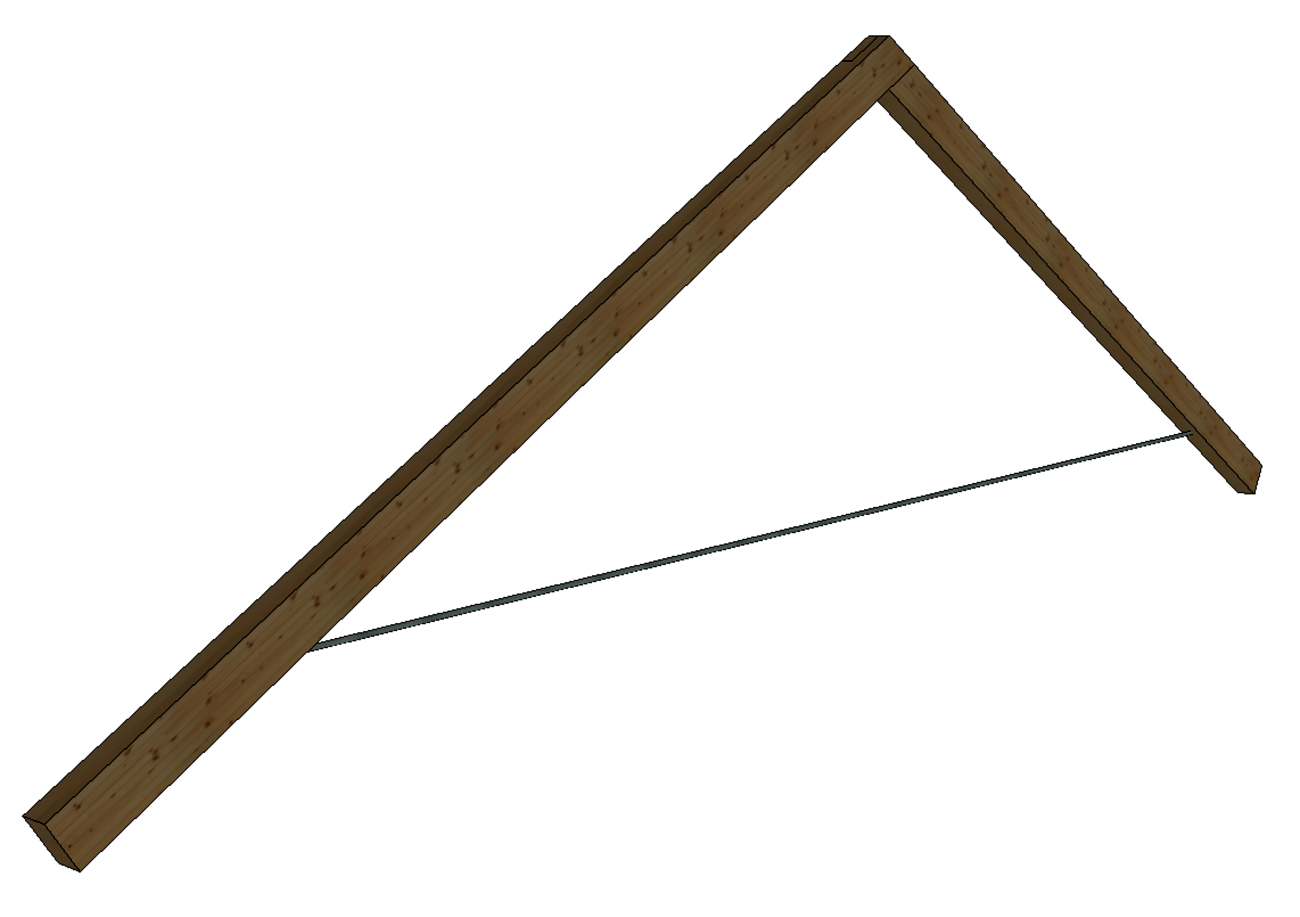
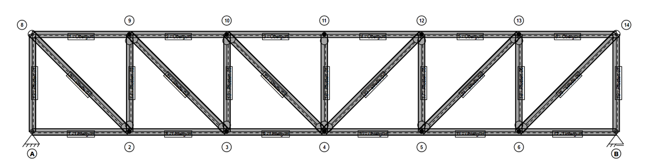
Steel components can be used to create load-bearing structures with small cross-sectional dimensions. In order to be able to design steel structures in DC statics, we have made it possible to calculate steel components in our bar system. This means that both pure steel bars and combinations of timber and steel cross-sections can be designed. Since tensile forces in particular are often transferred via steel components, we have expanded our component catalog to include round, square and rectangular steel profiles as solid cross-sections.
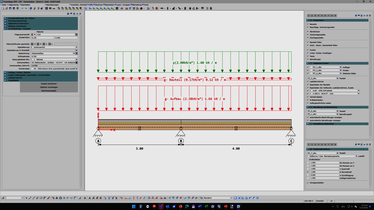
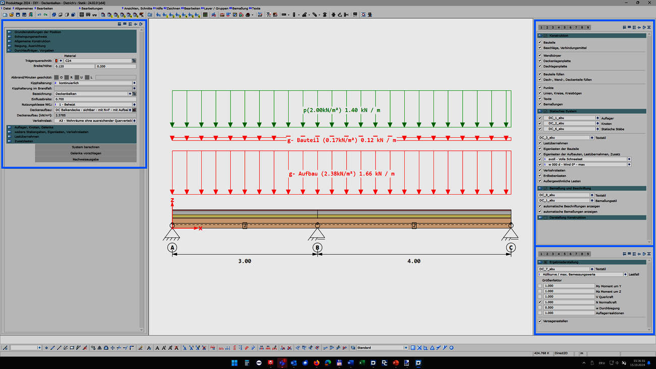
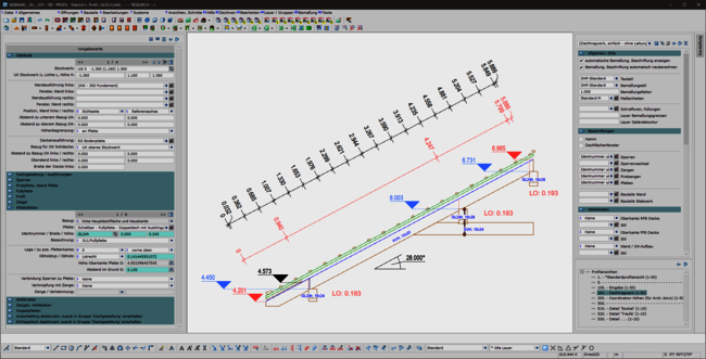
Palette dialogs are dockable dialogs at the edge of the screen that allow quick access to the respective functions. In DC-Statik, the dialogs for the general display (1-7-1) and results display (1-7-4) have been revised and can now be permanently displayed on the screen. To enlarge the graphics area, the dialogs can be folded to the side if required. The main dialog has also been updated so that it can be undocked or folded to the side. The new palette dialogs allow a permanent overview of all settings and quick switching between the desired screen elements.